Planning a DIY Drill Press Table Lift: What the Drawings Need to Show
Raising and lowering a drill press table by loosening the clamp and wrestling its weight is one of the machine’s small daily annoyances, especially with a heavy shop-built top on it. A table lift, a crank or screw mechanism that raises and lowers the table smoothly, solves it, and many people add one to a shop table. But a lift adds moving parts to something that must stay flat, square, and locked while drilling, so before you build, it helps to know exactly what the drawings need to show to get it right.
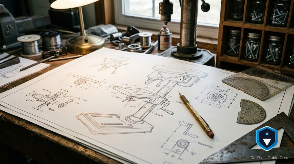
A DIY drill press table lift is a mechanism, usually a screw or rack driven by a crank, added to a drill press so the table raises and lowers smoothly and holds its height without being wrestled by hand. Useful drawings need to show the lift mechanism and how it mounts to the column, how it carries the table weight, how the table still locks solid for drilling, and how squareness is preserved.
Short answer: the drawings need to show the lift mechanism, a screw or rack and its crank, how it attaches to the column and bears the table’s weight, how the table stays square and level as it moves, and how it locks rigidly once positioned. A lift that raises the table but lets it tilt or wobble is worse than none, so the drawings must protect square, level, and a solid lock.
Show the lift mechanism and how it mounts
The drawings must first show the actual lift mechanism and how it attaches to the column, because that is the core of the build. Whether it is a threaded rod and nut, a rack and pinion, or a worm-driven screw, the plan should show the parts, how the crank turns the screw, and how the screw raises the table bracket. Just as important, it must show how the mechanism mounts to the column solidly, since the column carries the load and any loose or flexing mount lets the table sag or shift. Drawings that clearly show the mechanism and a solid column mount let you build a lift that actually bears the weight; vague ones leave the most important part to guesswork.
Show how it carries the weight
A table lift has to raise not just the factory table but often a heavy shop-built top and whatever is clamped to it, so the drawings need to show the mechanism sized and geared to carry that weight and hold it without slipping back. The plan should show the load path, from the table, through the bracket, into the screw or rack, and into the column mount, so you can see that each part is stout enough. It should also show that the crank effort is reasonable, a lift too hard to turn will not get used. Drawings that address the weight and the load path produce a lift that raises smoothly and stays put; ones that ignore it produce a mechanism that binds, slips, or sags.
Show how square and level are preserved
This is the detail that separates a good table lift from a frustrating one: the drawings must show how the table stays square to the spindle and level as it moves up and down. If the table rides on a single screw with no guide, it can tilt or rotate, throwing off every hole. So the plan should show a guide, a keyway, a second rail, or a close-fitting bracket on the column, that keeps the table from tilting or twisting as it travels. It should confirm the table returns to square at any height. Drawings that show how square and level are maintained through the travel are essential, because a lift that lets the table wander out of square defeats the whole point of the machine.
Show how it locks solid for drilling
Finally, the drawings need to show how the table locks rigidly once set, because during drilling the table must be as solid as if it had no lift at all. The plan should show a clamp or lock, often the original column clamp retained alongside the lift, that immobilizes the table against the downward force of drilling, so it cannot creep or bounce. A lift that positions the table but does not lock it firmly is unsafe and inaccurate. Drawings that show a solid locking method, separate from the lift mechanism, ensure the convenience of easy adjustment does not cost you the rigidity that accurate drilling demands.
Conclusion
Planning a DIY drill press table lift is about making sure the drawings show what actually matters: the lift mechanism and its solid column mount, how it carries the real weight of a loaded table, how the table stays square and level through its travel, and how it locks rigidly for drilling. A lift that raises the table but lets it tilt, sag, or bounce is worse than the wrestling it replaced. Insist on drawings that protect square, level, load capacity, and a solid lock, and you can build a lift that makes height changes effortless while keeping the table exactly as flat, square, and rigid as accurate drilling requires.
Frequently asked questions
What should a drill press table lift plan show? The lift mechanism and how it mounts to the column, how it carries the table’s weight, how the table stays square and level as it moves, and how it locks rigidly for drilling.
Why does the lift need a guide? Because a table riding on a single screw with no guide can tilt or rotate, throwing off every hole. A keyway, second rail, or close-fitting bracket keeps it square and level through the travel.
Does the lift replace the table clamp? No. The drawings should show a solid lock, often the original column clamp retained, that immobilizes the table for drilling. A lift alone does not hold the table rigid enough.
Can a lift handle a heavy shop-built top? Only if the drawings size and gear it for that weight and show the load path from table to column mount. A lift not built for the real load will bind, slip, or sag.
What lift mechanisms are common? A threaded rod and nut, a rack and pinion, or a worm-driven screw, each turned by a crank. The plan should show how the crank drives it and how it mounts solidly to the column.
Why is locking so important? Because during drilling the table must be as rigid as if it had no lift. A table that only positions but does not lock firmly can creep or bounce under load, which is unsafe and inaccurate.
References
- OSHA, Machine Guarding eTool: Drill Presses, osha.gov
- Vintage Machinery, machine tool references, vintagemachinery.org