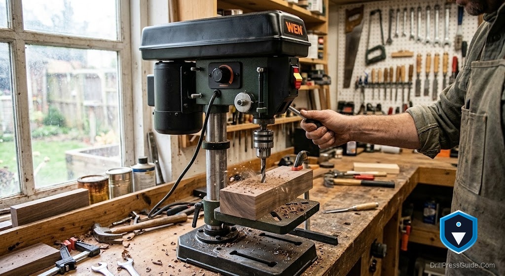
Planning a Drill Press Table: What the Drawings Need to Show

A good plan is worth far more than a photo of a finished table, because a plan tells you the dimensions, the materials, and the order of operations that make the build come out flat and square. When you are looking at free drill press table drawings, or sketching your own, the real question is whether the drawings show everything you need to build accurately. Plenty of plans look complete but leave out the details that actually decide whether the table works. Here is what a set of drawings needs to show.
A drill press table plan is a set of drawings and specifications for building a work surface that mounts on the drill press factory table, adding a larger flat area, a fence, and a replaceable insert. Useful drawings need to show the top construction and dimensions, the mounting method, the fence and its track, the insert, and how to square the finished table to the spindle.
Short answer: the drawings need to show a flat laminated top with clear dimensions, exactly how it mounts to the factory table, the fence and its track with the bit-clearance detail, the replaceable insert, and a squaring step. If a plan omits the mounting, the column clearance, or the squaring, it is incomplete no matter how nice it looks, because those are the details that make the table accurate.
The top: construction and dimensions
The drawings must first show the top clearly: what it is made of, how many layers, and its exact size. A good plan calls for two laminated layers of MDF or plywood for a flat, stiff panel, and gives length and width dimensions along with the layer thickness. It should show any edge banding and where the insert opening and fence track are cut. Dimensions matter because the top must support your work without hitting the column, and flatness matters because it sets the table’s accuracy. Drawings that show the top’s construction and give real numbers let you build a flat, correctly sized surface; vague ones leave you guessing at the most important part.
The mounting: how it attaches
The single most commonly missing detail is how the table attaches to the factory table, and it is essential. The drawings need to show the mounting holes or slots, positioned to line up with the factory table’s existing holes, and the hardware, bolts into threaded inserts or captured nuts in the top, that holds it solidly. They should show fasteners countersunk flush on the working surface so nothing snags. Friction mounting is not enough, since a table that shifts under load drills inaccurately. If a plan does not clearly show the mounting, you cannot build a table that stays put, so treat the mounting drawing as a must-have, not an optional detail.
The fence, track, and column clearance
The drawings should show the fence as straight, stable stock, tall enough to support work, and how it mounts, usually a T-track set into the top with dimensions for the track location. Critically, the plan needs to show column clearance, that the fence and its travel clear the chuck and column through the full spindle stroke, because a fence that fouls the column at depth is a classic failure the drawings should rule out. A bit-clearance gap or slot in the fence and an optional dust port are worth showing too. When the drawings detail the fence, its track, and the column clearance, you can build a fence that positions work and locks square without hitting the machine.
The insert and the squaring step
Finally, the drawings need to show the replaceable insert, a snug, flush square of the same material set directly under the spindle, so the plan makes clear where the opening goes and how the insert sits flush to back up the work and prevent tearout. And the plan should include a squaring step: check the surface is perpendicular to the bit with a reliable square, adjust or shim, and confirm with a test hole in scrap, then square the fence. Many drawings stop at the physical build and omit squaring, but without it the table is not truly finished. Drawings that show the insert and the squaring step give you a table that is accurate, not just assembled.
Conclusion
When judging or drawing up a drill press table plan, look past the finished-photo appeal and check that the drawings actually show what you need: a flat laminated top with real dimensions, a clear mounting method to the factory table, the fence with its track and proven column clearance, the replaceable insert, and a squaring step. A plan missing the mounting, the clearance, or the squaring is incomplete, because those are precisely the details that decide whether the table comes out flat, secure, and square. Insist on drawings that show them, and you can build a table that turns the small factory surface into a precise, versatile work platform.
Frequently asked questions
What should a drill press table plan show? The top’s construction and dimensions, exactly how it mounts to the factory table, the fence and its track with column clearance, the replaceable insert, and a step for squaring the table to the spindle.
What detail do plans most often leave out? The mounting method and the squaring step. Without a clear mounting to the factory table the top shifts, and without squaring the finished table drills inaccurately, so both are essential.
Why do the top’s dimensions matter? Because the top must support your work without hitting the column, and be flat and stiff. Real length, width, and layer dimensions let you build a correctly sized, flat surface.
What is column clearance and why show it? It is confirmation that the fence and its travel clear the chuck and column through the full spindle stroke. A fence that fouls the column at depth is a common failure good drawings rule out.
How should the plan show the table mounting? With mounting holes or slots aligned to the factory table’s holes and hardware bolting into inserts or captured nuts in the top, fasteners countersunk flush, not relying on friction.
Does the plan need a squaring step? Yes. A plan that stops at assembly is incomplete. It should show checking the surface perpendicular to the bit, adjusting or shimming, and confirming with a test hole, then squaring the fence.
References
- Forest Products Laboratory, wood machining and construction references, fpl.fs.usda.gov
- OSHA, Machine Guarding eTool: Drill Presses, osha.gov